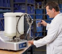
Ratio check - dispensing two-component materials
Ratio check - dispensing two-component materials
It is not uncommon for materials to be divided into two components for processing. One is typically defined as the “base” and the other is typically called the “catalyst”. In most material chemistries, the mix ratio of these is a critical element to achieve proper curing and the physical properties after cure. The integrity and quality of the assembly is at stake if these ratios are not within the specifications listed by the material supplier.
Graco develops and manufactures the meter mix and dispense equipment designed to consistently deliver materials on ratio and shot amount. Once this equipment is set up, one way to verify that all components are functioning and processing as designed is to check the ratios of the material. Usually a complete solution will consist of supply systems, metering pumps and a dispense valve. The ratios are most often checked at the dispense valve as this is the last point before the components are dispensed into either a set of cartridges or mixing chamber. Checking ratios routinely is a good way to validate the process to ensure mix quality and equipment integrity.
Key components to ratio checking
A primed system
Ensure the system is fully primed with no air trapped in any hose, pump or valve. If any air is trapped within the system, the results of the ratio study will not be repeatable nor stable and will likely show the system to be off ratio.
Container tare
Tare the containers individually each time. Not all cups are identical, even if they look the same. If the scale is not tared out after each new cup, the results could appear skewed. For smaller shot amounts or wider ratios, a small variation in cup weights is likely to show up in the ratio measurement if they are not tared out on the scale every time.
Stable system pressures
With the ratio check nozzle attached, ensure that the system is purged to a constant pressure. If purge shots are not taken and ratio measurements are done, the first few shots are likely to be skewed from the rest as the system pressure builds.
Flow rate
For optimal process validation, the production flow rates should be targeted.
Shot size
The shot size used in the process should be targeted for ratio checking as well. If a continuous dispense or material saving is critical, the shot size should be no less than 15% of the sum of the metering pump volumes.
Ratio checking procedure
- De-energise the system.
- Inspect the ratio check nozzle prior to installation to ensure all seals are in place and intact.
- Install the ratio check nozzle at the nose of the dispense valve. Torque to the required specification.
- Input the settings into the ADM (Advanced Display Module) or alternate control device for the desired shot amount. The shot amount used in the application of this machine should be targeted. If it is a continuous dispense or material savings that is critical, the shot size targeted should be no less than 15% of the sum of the pump volumes.
- Adjust the settings on the machine in order to produce the desired flow rate. Ideally, the application flow rate settings should be used.
- Place an empty container under the ratio check nozzle.
- Take a series of purge shots until the pressures have stabilised. This also helps to prime the ratio check nozzle.
- Tare out a set of containers on the scales, noting which cup goes with which scale.
- Place the containers under the ratio check nozzle with one container under each component stream.
- Take a shot into the sample containers.
- Place the containers back on the scales and record the measurements. The weight ratio can be determined from these measurements. If a volume ratio is desired, measure the specific gravity of each material side and use it in converting the mass of the samples to volumes.
- Repeat steps 8 through to 11 for the desired number of shots.
What if the ratios are out of specification?
If ratios over time have trended to values outside of what the specification calls for, there are some general items that should be checked or verified. Many times it depends on the particular dispensing solution and that particular manual should be referenced.
- Check for cavitation of the system including in the supply pumps. Check feed pressures to make sure they meet the requirements as defined by the particular metering solution. Check the material level in the supply system.
- Possible seal wear in the metering pumps.
- Blockage in the system due to material curing or filter clogging or material separation leading to packing out of the filled elements of the material.
- Leakage from hose or fitting connections.
- Air entrapments can typically be a result of material drum changeovers or disconnecting and reconnecting of hoses or fittings.
Contact an expert
Related Articles
Electric vehicle thermal management
Whether it’s assembling electric vehicle (EV) batteries, and electronic products, or miniaturizing printed circuit boards (PCBs), thermal management remains crucial to longevity, efficiency and safety.
Factory Keeps EV Battery Pack and Module Production Moving with Elite
Electric vehicle battery performance and safety rely on effective application of thermal interface material. TIM is known to cause production headaches on EV battery assembly lines. Learn how a large automotive manufacturer solved that problem.


